RS-232 Basics (Part 1): Scale Pinout and Cable Wiring

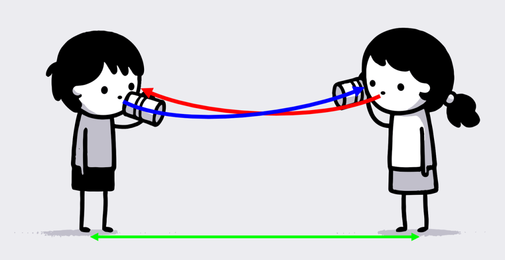
RS-232 has been around since the 1960s, so it seems appropriate to start this article with a communication method that’s even older: the tin can phone.

The kid on the left is speaking into a can held in front of their mouth (transmitting data, TD), while the other is listening through a can held to their ear (receiving data, RD).

To enable both kids to speak (TD) and listen (RD) at the same time, they would require a second set of cans connected by a string, represented by the red arrow1. Let’s also mark the ground (GND) in green:

At this point, the illustration looks similar to what you might find in the RS-232 section of your scale’s user manual2:

RS-232 schematic: Scale to PC connection using a crossed cable

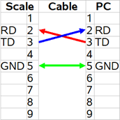
To establish bidirectional communication with this scale, you would need to connect the transmit data pin (usually called TD or TXD) to the receive data pin of your computer (RD or RXD) and vice versa. Additionally, it’s essential to connect the ground pins (GND) for reference3.

Although this seems simple, attempts to establish communication with a scale using RS-232 often fail at this basic stage.

To understand why this is such a common problem, take a look at the photos of the RS-232 interface of A&D’s popular FX-120i balance and Radwag’s PUE C32 weighing indicator:

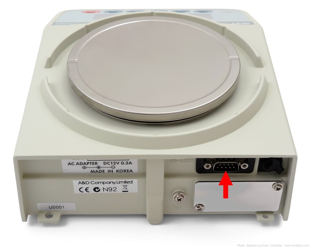
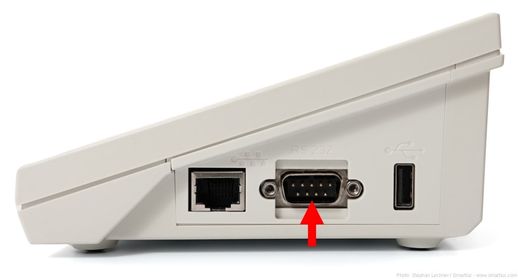
Both weighing instruments have a male D-sub port with 9 pins (DE-9M, frequently but incorrectly called DB-9M)4. You might therefore think that they can use the same cable. You would be wrong, as their pinout is not identical:

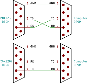
Radwag’s PUE C32 receives data (RD) on pin 2 and transmits it on pin 3 (TD), requiring a crossed cable when connected to the standard DE-9M port of a PC. A&D’s FX-120i receives data on pin 3 (RD) and transmits it on pin 2 (TD). It requires a straight cable.

RS-232 cable terminology

Null modem cables are also known as crossover or crossed cables. They cross-connect certain pins, such as RD and TD.

Straight cables run straight through and are also called straight-through cables or 1:1 cables.

There are other types of serial cables, but these two are most common.

If you use the wrong type of cable, you connect TD to TD and RD to RD. This would lead to a situation like the one illustrated below, where both kids are holding the cans to their ears and no communication is possible:

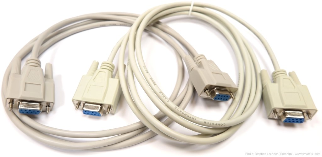
While we can immediately recognize that something is wrong in this picture, no one can tell a straight cable from a null modem cable just by looking at it:

Key takeaways: The fact that you can plug in a cable means nothing – it’s the pinout of your weighing instrument and the wiring of your cable that matters.

If the electrical connection between your scale and computer is not established correctly, it does not matter which software you use. It will not receive any data.

There are many more aspects of RS-232 communication to explore – we’ll do that in future articles. In the meantime, don’t hesitate to leave a comment, but please understand that I can’t remotely diagnose communication problems for free.


1Bidirectional communication on a single string is technically possible but doesn’t seem very practical.

2Did you notice that this schematic doesn’t tell you the gender of the port (DE-9M or DE-9F)? While it was just a simplified example, many actual user manuals omit this information as well, adding to the general confusion surrounding RS-232.

3Some scales and balances require connections between other pins. This is an advanced topic for a future article.

4RS-232 ports on scales come in many different forms and are not limited to DE-9M. You’ll frequently encounter DE-9F, DB25 (especially on older balances), RJ11, RJ45, and many others.

Using verified Ohaus SJX scales with our software

Most class I and II weighing instruments use what is called an “auxiliary indicating device” with a “differentiated scale division”1: On the display, the final digit or digits are visually distinct from the others. This is also the case with Ohaus SJX scales that have been verified (e.g. the SJX6201M):

Note how the scale division (d) is one tenth of the verification scale division (e) when weighing in g

This digit is enclosed in square brackets when the weight is sent over one of the optional interfaces (such as RS-232, USB, or Ethernet). Example:

   1234.[5]     g

By default, our software does not capture a digit that comes after a non-numeric character. This can be easily fixed in two steps. We’ll use screenshots from Simple Data Logger as an example, but the procedure is basically the same for our 232key virtual keyboard wedge software2.

1. Change the regular expression used to capture the weight

In the Input tab, click the Customize button and replace the regular expression with the following one:

(-*[0-9]*\.?[0-9]*\[[0-9]+)

This will ensure that the opening square bracket and the last digit are also captured (shown in blue in the Event Log):

Remove the bracket

The string we’ve now captured is not a number because it contains a bracket. Writing it to a file like this would make things complicated when processing the data later.

Fortunately, you can easily remove the bracket: Go to the Process tab, check Enable Editing, and enter the opening square bracket “[” in the Remove characters field:

SDL will now properly write the complete weight as a number to the CSV file, which can be opened in Excel or other programs:

Important: If you are utilizing our software in connection with a verified scale, please ensure that such usage is compliant with the regulations and requirements of your local jurisdiction.


1: See OIML R76 (PDF) for further information
2: For an example that uses 232key, see this article

A GX16 connector that does not fail

If you’re working in the weighing industry, you’ve probably come across the GX16 connector:

GX16 connector
Typical GX16 connector (male)

This circular connector is named after its M16 thread and can have up to 8 pins. While it is frequently referred to as an “aviation connector”, I sincerely hope that it is not actually used in aircraft, as I’ve seen many of these connectors fail. Their tiny screws are prone to coming loose, which renders the strain relief useless. Then it’s only a matter of time before the cable is pulled too hard and the wires detach.

What does it take to make a reliable GX16 connector?

This is the Ohaus Catapult 5000 scale:

Ohaus Catapult 5000 scale

It uses an overmolded GX16 connector to connect the platform to the indicator:

Ohaus Catapult 5000 scale indicator

We’ve sold hundreds of these scales and never had an issue with them that was caused by the connectors. This is due to the extensive work that Ohaus put into making them, as demonstrated by the photos below. Apologies for the photo quality, I didn’t take them in our photo studio and it shows.

Completely disassembled GX16 connector
Disassembly of the overmolded Ohaus Catapult 5000 GX16 connector (female) reveals that it contains a complete regular connector, including the metal backshell
The screws of the strain relief are secured with heat shrink tubing
The connector is completely filled
After removal of some material
Further material removal reveals that heat shrink sleeves were used after soldering

Further info