In this article, I’ll show you how to capture the weight (and tare weight) from an Ohaus Defender 3000 scale using BarTender while avoiding an issue that would otherwise lead to the scale showing only “Print” on its display.
Notes:
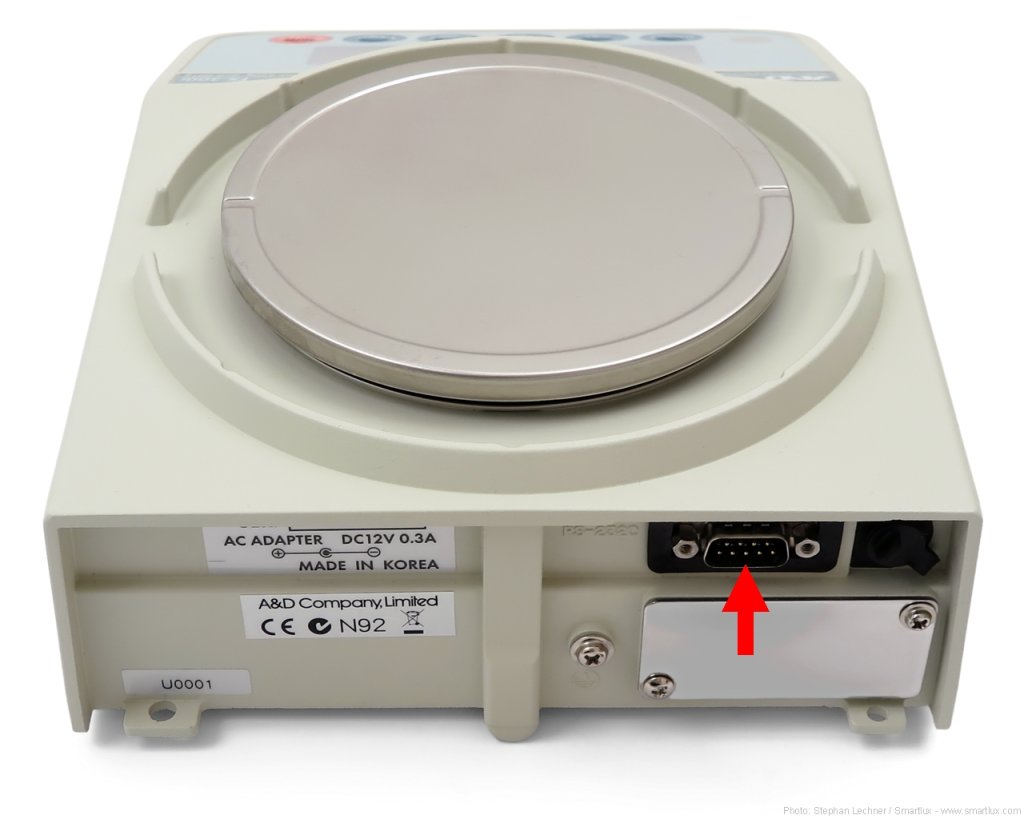
This guide applies to the new generation of Ohaus Defender 3000 scales launched at the end of 2021/beginning of 2022. The picture below shows the new indicator on the right and its predecessor on the left.

It was created using Bartender Designer 2022 R8 and version 1.04 of the Ohaus Defender 3000 firmware. Future versions might make things easier (or more difficult, as seems to be the general trend).
Can you use existing Ohaus scales defined in BarTender?
Let’s try it out. In the menu, go to Administer > Weighing Scale Setup:

If no scale has been defined yet, this will launch the Add Scale Wizard (otherwise, click on Add Scale in the windows that appears):

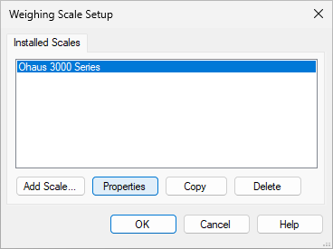
After clicking next, you’ll be able to select “Ohaus” as the manufacturer and you’ll see a number of supported models. Select “Ohaus 3000 Series” (as this sounds most similar to “Ohaus Defender 3000 series”):

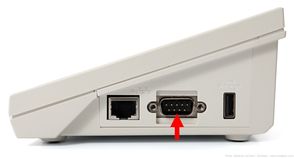
Continue by specifying the connection method. If your scale is connected via USB or RS-232, you’ll also have to choose the COM port and confirm the interface parameters (Flow Control is set to XON/XOFF by default, it doesn’t really matter):

Click next on all further steps of the wizard. After completing it, we can now test the scale. Select it and click on Properties:
In the window that opens, switch to the Connection tab, then click on Test Connection:

Bartender will start sending the “IP” (Immediate Print) command to the scale to request the weight. It does so multiple times per second (4 times by default). It seems to capture the net weight correctly (5.005 kg in the screenshot below):

However, there are at least two issues with this method.
1. The scale shows “Print” all the time
When the scale receives the “IP” command, not only does it reply by sending the weight, but it also shows “Print” on its display. As BarTender sends this command multiple times per second, “Print” is all that you’ll see:

My opinion: Displaying “Print” when the user presses the Print button on the scale is useful (it gives the user feedback). Displaying it when the “P” command is received can be justified by saying that the scale should behave just as if the user had pressed the physical button. However, displaying it when the scale receives “IP” does not make much sense to me. I’m hoping Ohaus will reconsider this and change it in a firmware update. Until then, you can use the solution described below.
2. You cannot use a tare weight
The second issue I found is that once you’ve used the scale’s tare function, BarTender is no longer able to capture the net weight (and it also can’t capture the tare weight):

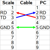
Solution: Define a new scale that uses the MT-SICS protocol
Unlike its predecessor, the new Defender 3000 supports (some) MT-SICS commands. The MT-SICS equivalent to the “IP” (Immediate Print) command is the “SI” (send immediately) command1. Fortunately, the scale replies to this command without displaying “Print”. Moreover, it also supports the “TA” command that BarTender uses with MT-SICS Level 1 scales to request the tare weight.
Note: You can explicitly set the scale to “SICS” by going into the “Print” menu (for RS-232) or “Print1” (for USB or Ethernet) and setting “Assignment” to “SICS”, but this was not necessary in my tests.
Let’s start the Add Scale Wizard again, but this time, you don’t select an existing model. Instead, choose Define a model not listed above:

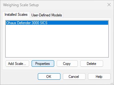
Then, select Ohaus as the manufacturer and enter a name for your new model, e.g. “Ohaus Defender 3000 SICS”. Under Protocols Supported by this Scale, select “Mettler Toledo (MT-SICS Level 1)”:

Continue with the Wizard as before.
I used this opportunity to test the optional Ethernet interface of the new Ohaus Defender 3000. I set it to acquire an IP address via DHCP (which is out of the scope of this tutorial), connected it to our network and then copied its IP address from the menu under Ethernet/IP Address. The port (which is also displayed by the scale) is always 9761:

You can – of course – still connect to the scale using a COM port.
After completing the Add Scale Wizard, it is again time to test the connection. Click on Properties:
In the new window, switch to the Connections tab and click on Test Connection:

You’ll now see that the net weight and tare weight are acquired correctly:
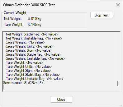
Furthermore, the scale’s display now shows the weight instead of just “Print”.
Conclusion
The new Ohaus Defender 3000 scales are compatible with BarTender, but initial setup is not quite as straightforward as one might expect. You’ll get the best results by defining a new scale that uses the MT-SICS protocol (which the new Defender 3000 supports, unlike its predecessor).
I hope this tutorial is helpful. Please don’t hesitate to leave a comment, but please note that I am in no way a BarTender expert and that answering BarTender-related questions is not something I particularly enjoy. I suggest using the BarTender’s Online Help system or contacting Seagull Scientific if you need support with their software.
- Well actually, the equivalent would be “SIU” (send immediately in display unit), but this article is long enough and “SI” is the better choice anyway. ↩︎