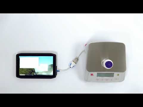
I’ve made a short, but comprehensive walkthrough video on connecting an Ohaus Valor 7000 scale to a PC. It uses the standard RS-232 port, a suitable data cable, an RS-232-to-USB converter and our free 232key virtual keyboard wedge software.
This will enable you to transfer the weight directly into a variety of applications as simulated keystrokes, such as Excel, a LIMS, or any other application of your choice. It even works with browser-based applications!
This guide can also be used for the very similar scales from the popular Ohaus Ranger 3000 series.
Video transcript
Introduction
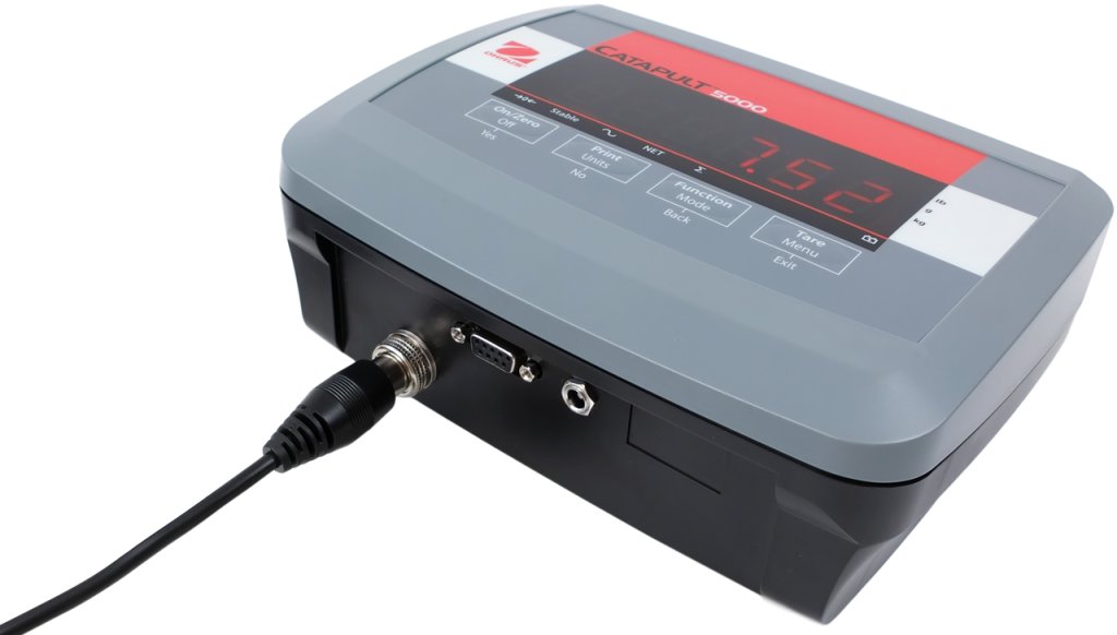
This video will show you how to connect your Ohaus Valor 7000 scale to a PC and configure the 232key Virtual Keyboard Wedge software.

Connect the RS-232 cable to the scale
To prevent accidental overloading of the scale, remove the weighing pan and pan support. Then turn the scale upside down.
Open the compartment on the bottom. Connect the serial cable and secure it with the thumb screws.

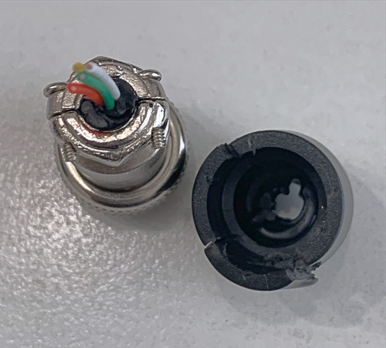
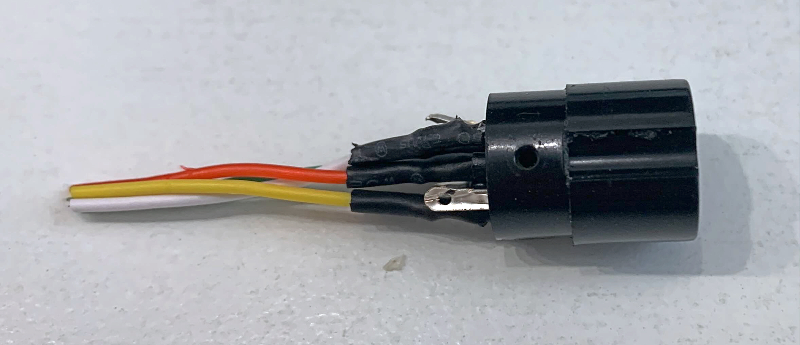
Remove the cable breakaway tab
Before closing the compartment, break the middle tab on the cover. Turn the balance back over and put the weighing pan back in its place.

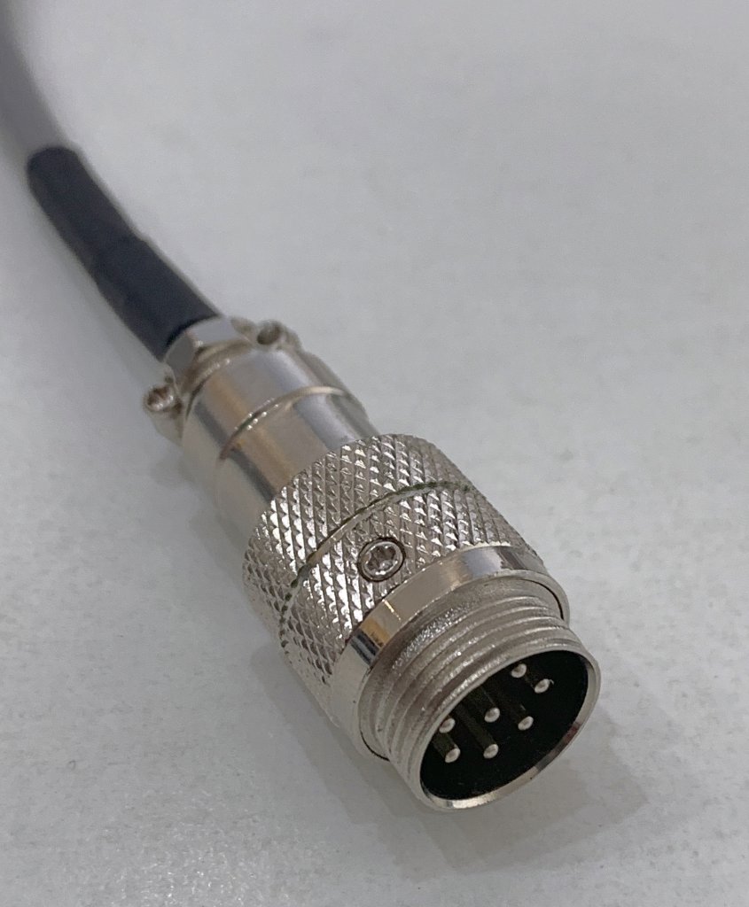
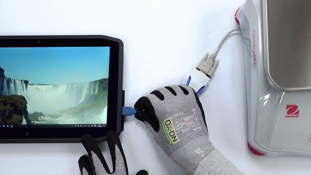
Connect the USB converter to the RS232 cable
Connect the USB converter to the other end of the cable and secure it with the thumb screws.

Connect the USB converter to your PC
Plug the converter into a USB port on your PC. The driver should install automatically. If not, see the video description for download links.
After the device is recognized by Windows, a new COM port will appear. You can find this port in the Windows Device Manager under “Ports (COM & LPT)”. In our case it is called COM9, but the number will probably be different on your system.
Configuring 232key
Download and install 232key, then launch the application.
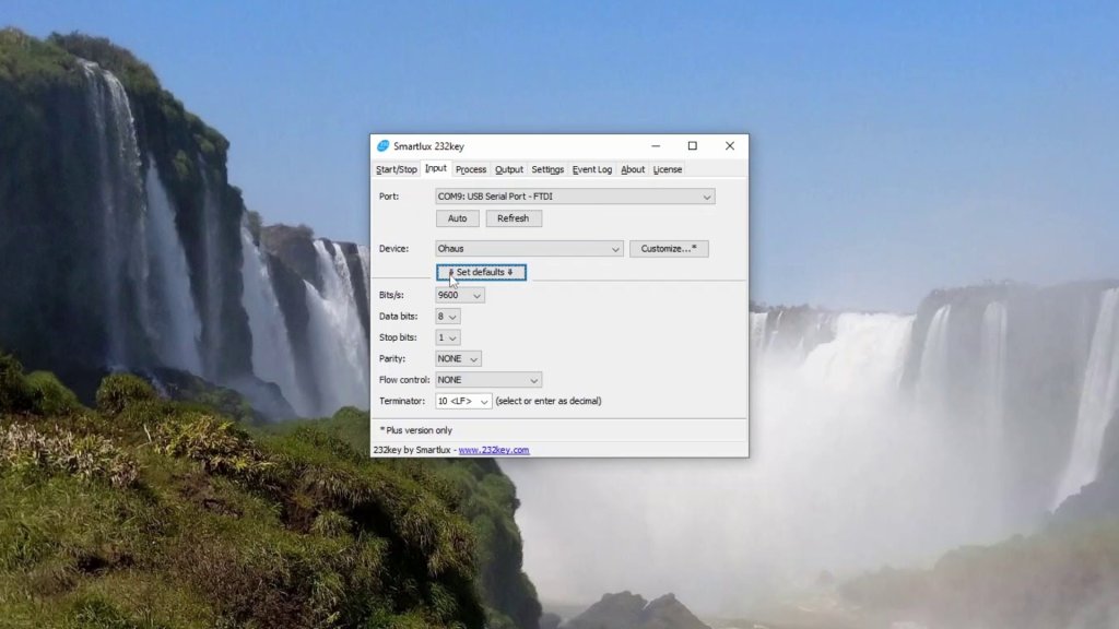
In the “Input” tab, select the new COM port.
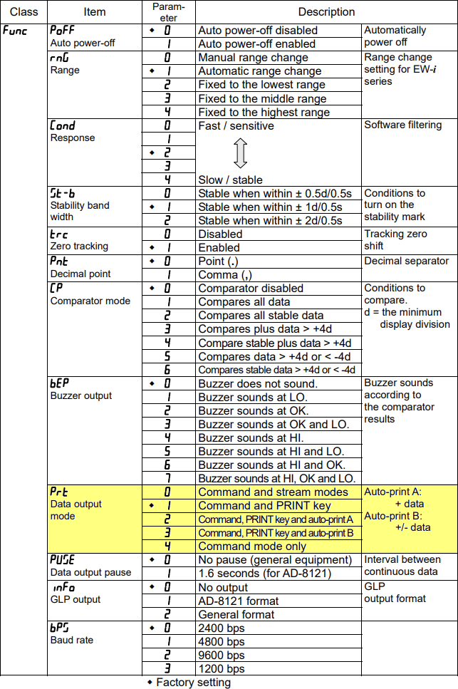
Set the “Device” to Ohaus and press the “Set defaults” button to set the serial interface parameters.
In the “Output” tab, select your keyboard type and, if necessary, a key that should be “pressed” after the weight is entered.
Go to the “Start” tab and press the “Start” button. 232key will now start listening for incoming data on the specified COM port and output it as simulated keystrokes.
Switch to the target application, e.g. Excel or a LIMS. For testing purposes we’ll just use Notepad.
Transfer the weight
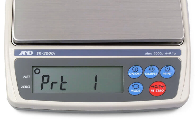
Turn the scale on. Place an object on the weighing pan and press the PRINT button.
The weight is entered into the target application.

For more information, please visit our website at 232key.com.