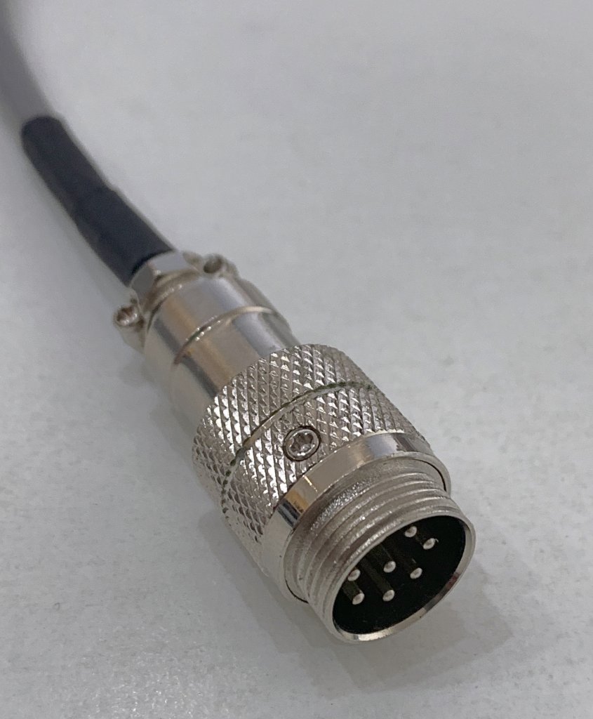
If you’re working in the weighing industry, you’ve probably come across the GX16 connector:
Typical GX16 connector (male)
This circular connector is named after its M16 thread and can have up to 8 pins. While it is frequently referred to as an “aviation connector”, I sincerely hope that it is not actually used in aircraft, as I’ve seen many of these connectors fail. Their tiny screws are prone to coming loose, which renders the strain relief useless. Then it’s only a matter of time before the cable is pulled too hard and the wires detach.
What does it take to make a reliable GX16 connector?
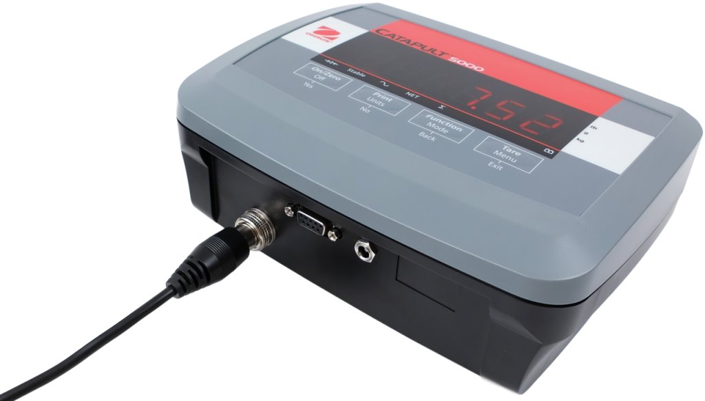
This is the Ohaus Catapult 5000 scale:
It uses an overmolded GX16 connector to connect the platform to the indicator:
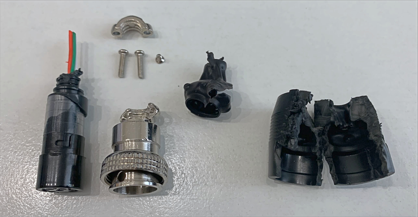
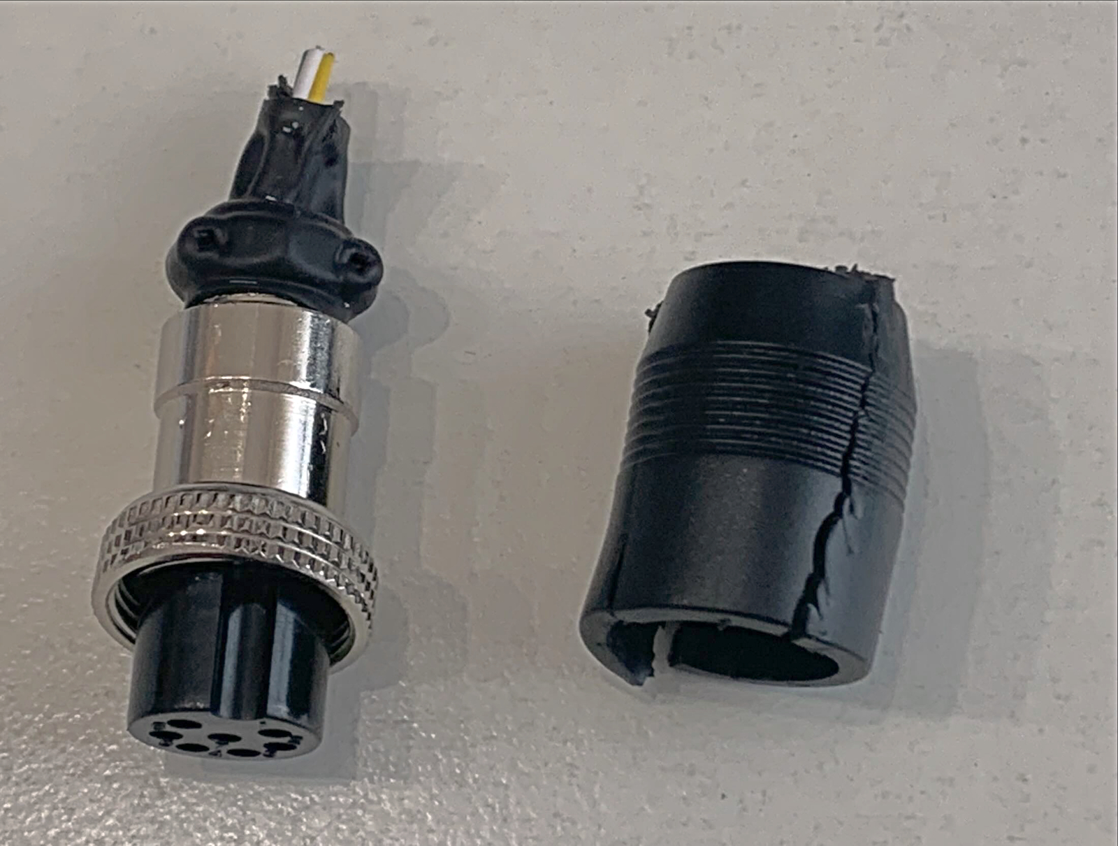
We’ve sold hundreds of these scales and never had an issue with them that was caused by the connectors. This is due to the extensive work that Ohaus put into making them, as demonstrated by the photos below. Apologies for the photo quality, I didn’t take them in our photo studio and it shows.
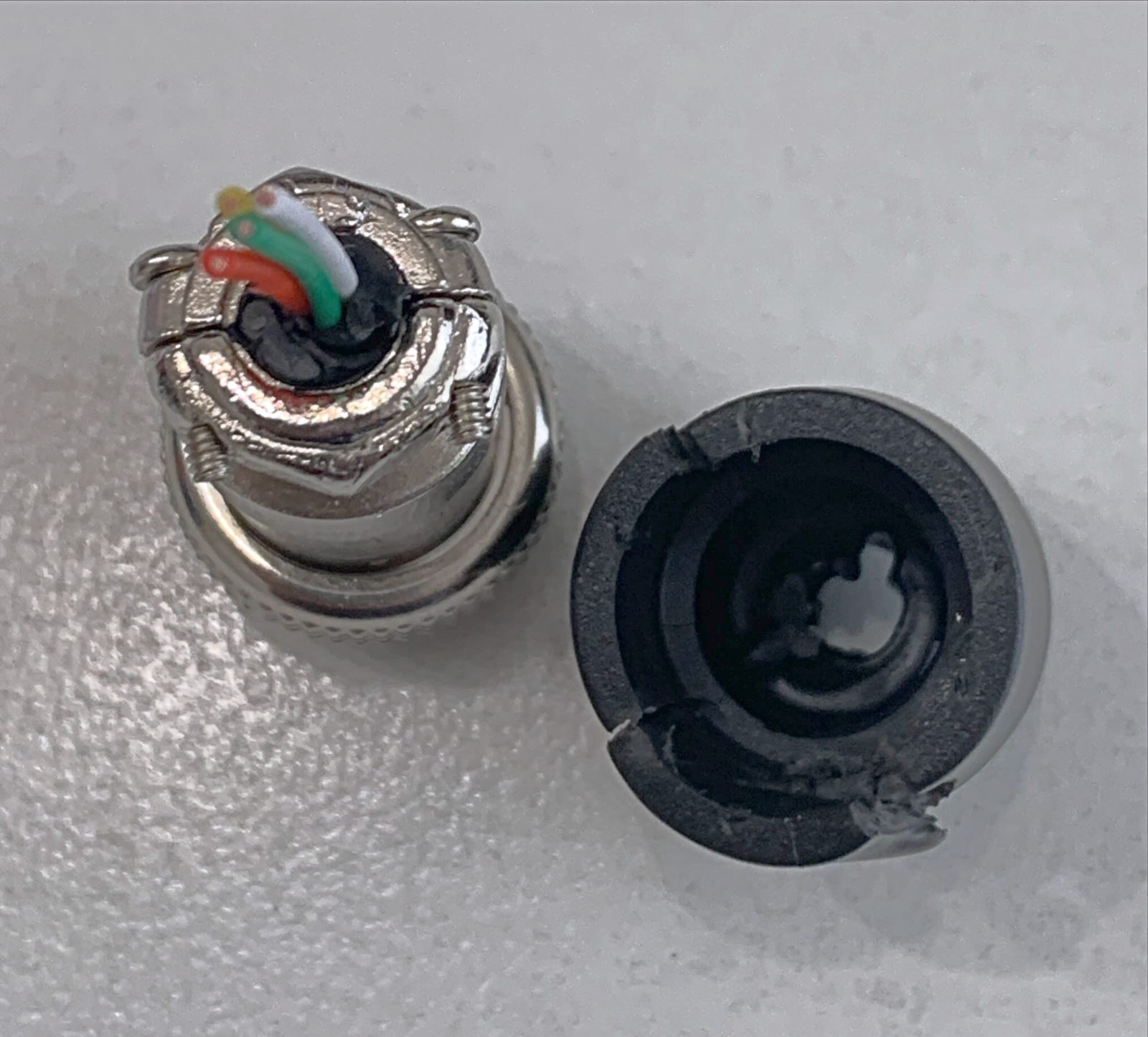
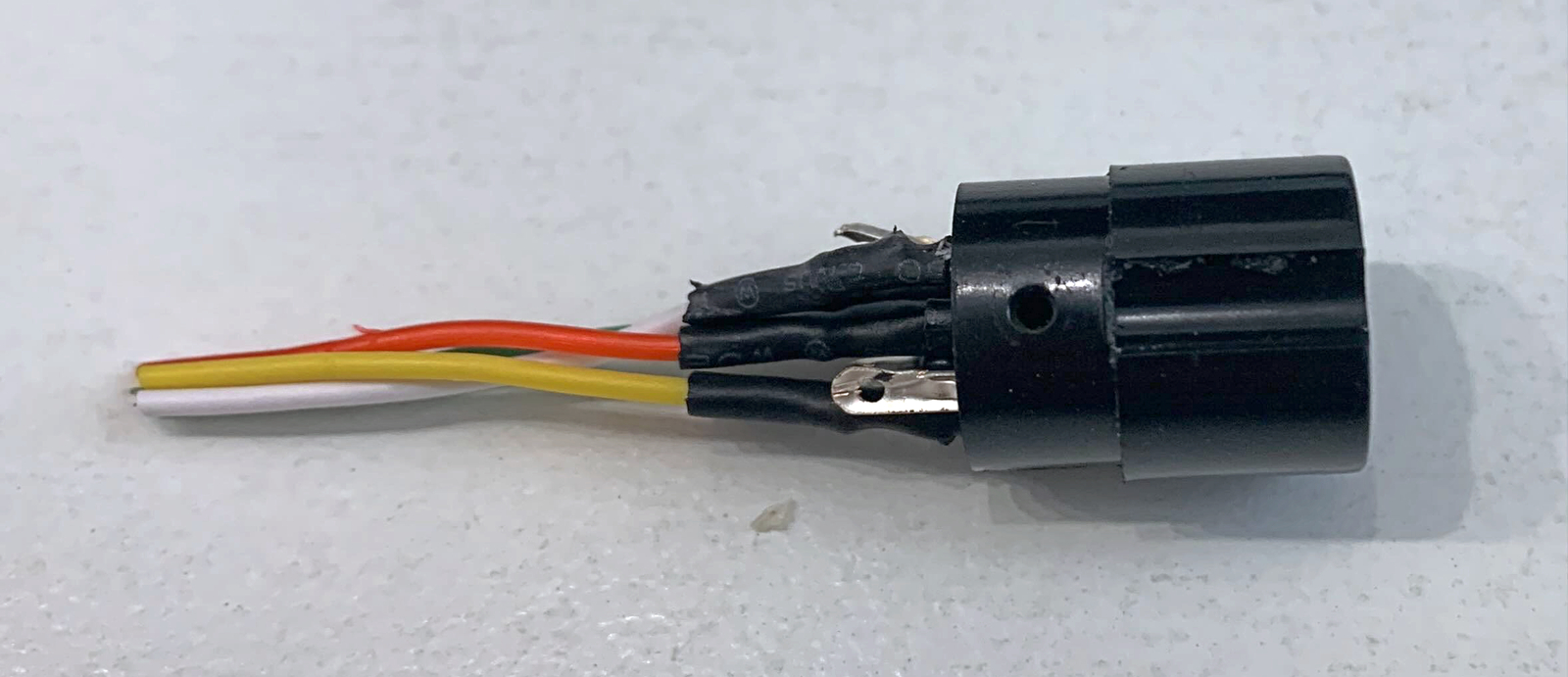
Disassembly of the overmolded Ohaus Catapult 5000 GX16 connector (female) reveals that it contains a complete regular connector, including the metal backshellThe screws of the strain relief are secured with heat shrink tubingThe connector is completely filledAfter removal of some materialFurther material removal reveals that heat shrink sleeves were used after soldering
RS-232 is still the most popular interface for balances and scales. It is often described as “simple”, however, when things don’t work as expected, finding the cause can be difficult.
When you’ve tried everything and still can’t reliably communicate with your scale via RS-232, there’s a chance a fake chip may be the cause.
Just a few weeks ago, the thought of encountering counterfeit ICs in digital scales had not crossed my mind. Thanks to FTDI’s recent attempt to “brick” counterfeits via Windows Update, fake chips are now a hot topic on the web. While I don’t agree with the way FTDI tried to punish the end user, I wish the controversy had occurred a few weeks earlier. This would have saved me a lot of time.
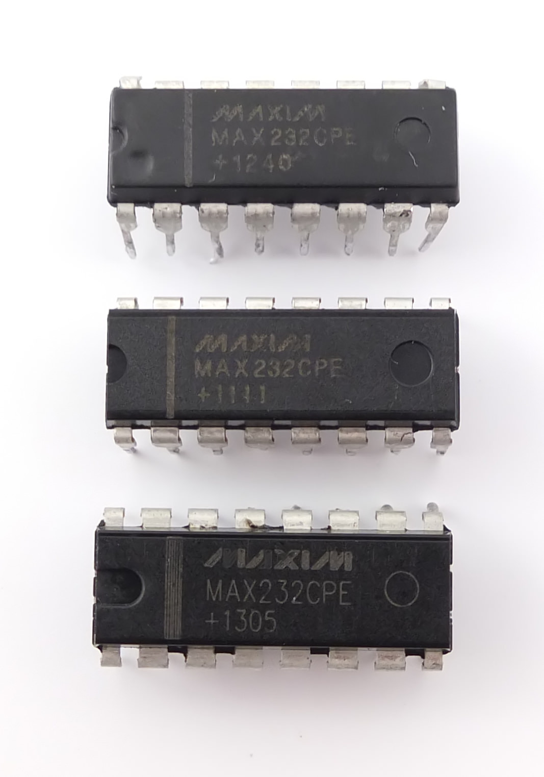
Back then I was doing the final QC for several scales which were about to be shipped to a customer. The last item on my checklist was “bidirectional communication using RS-232”, something I had done many times before with this exact model. What should have taken a few minutes ended up taking me several days and nearly drove me crazy because the problems I encountered were difficult to replicate. Eventually, I arrived at the conclusion that something was very wrong with the MAX232CPE+ chips, which are responsible for converting TTL signals to RS-232 levels. After doing some research on the internet*, I started to suspect those chips were counterfeit. It seemed like a far-fetched idea** at the time, but I still desoldered them, took a few pictures and sent them to Maxim Integrated.
Fake MAX232CPE+ and MAX232EPE+
Fake, fake and fake.
Thankfully, I received a reply in less than two hours:
“Yes these parts are counterfeit, they do not match markings of lots we manufactured.”
Now extremely suspicious of all MAX232s***, I disassembled a few more scales from 4 different vendors. 3 contained ICs belonging to the MAX232 family, so I sent the pictures to Maxim Integrated, too. In addition to the chips used by the scale manufacturer which had prompted me to start this investigation, one chip used by another manufacturer was also flagged as counterfeit.
Counterfeit MAX232EPE+
To be fair, my sample size is too small to draw meaningful conclusions regarding the entire weighing industry. However, if you’re in the business of making weighing instruments and were blissfully unaware of this issue, I hope this article serves as a wake-up call.
** Though not quite as far-fetched as the manufacturer’s idea that “static build up from the polystyrene packaging in road transportation” was to blame.
*** And also seriously angry at having wasted so much time doing something the manufacturer should have done. I won’t do any naming and shaming here, though.
Update October 3, 2017: Several articles concerning this issue have appeared since I originally wrote this blog post.
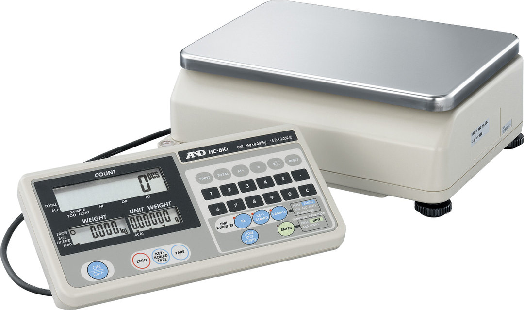
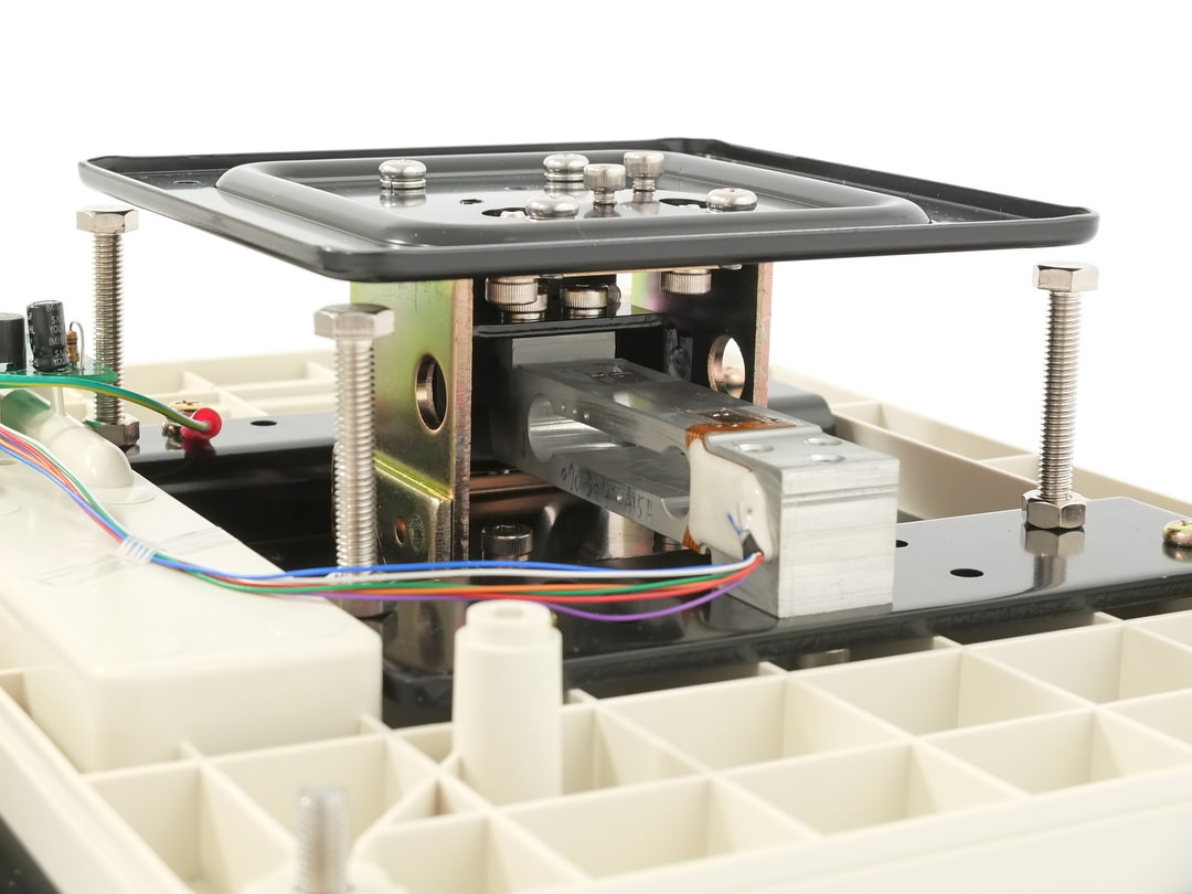
One of the interesting features of A&D’s HC-i counting scale is its modular construction. The indicator can be separated from the base:
The following image lets you have a look inside the base of the scale. You can click on the tabs to highlight different elements and read a short description:
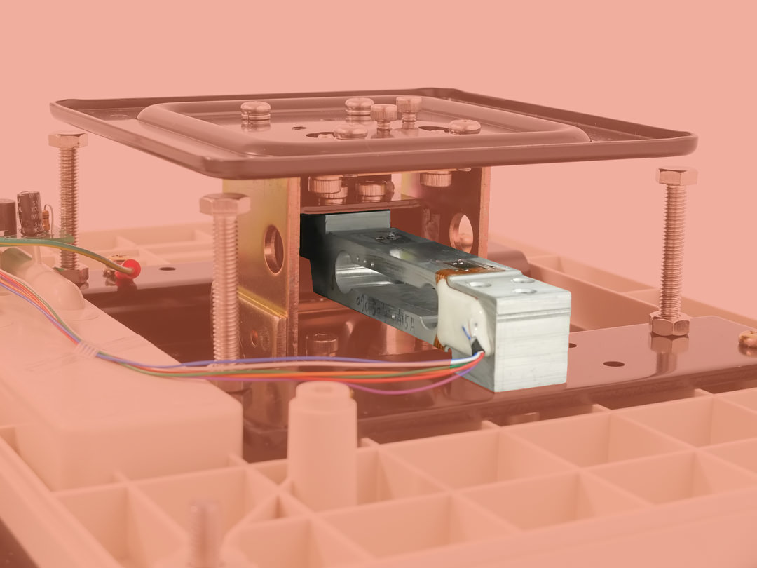
The load cell is attached to the bottom plate on one end and to the top plate on the other. It will slightly bend when a load is applied.
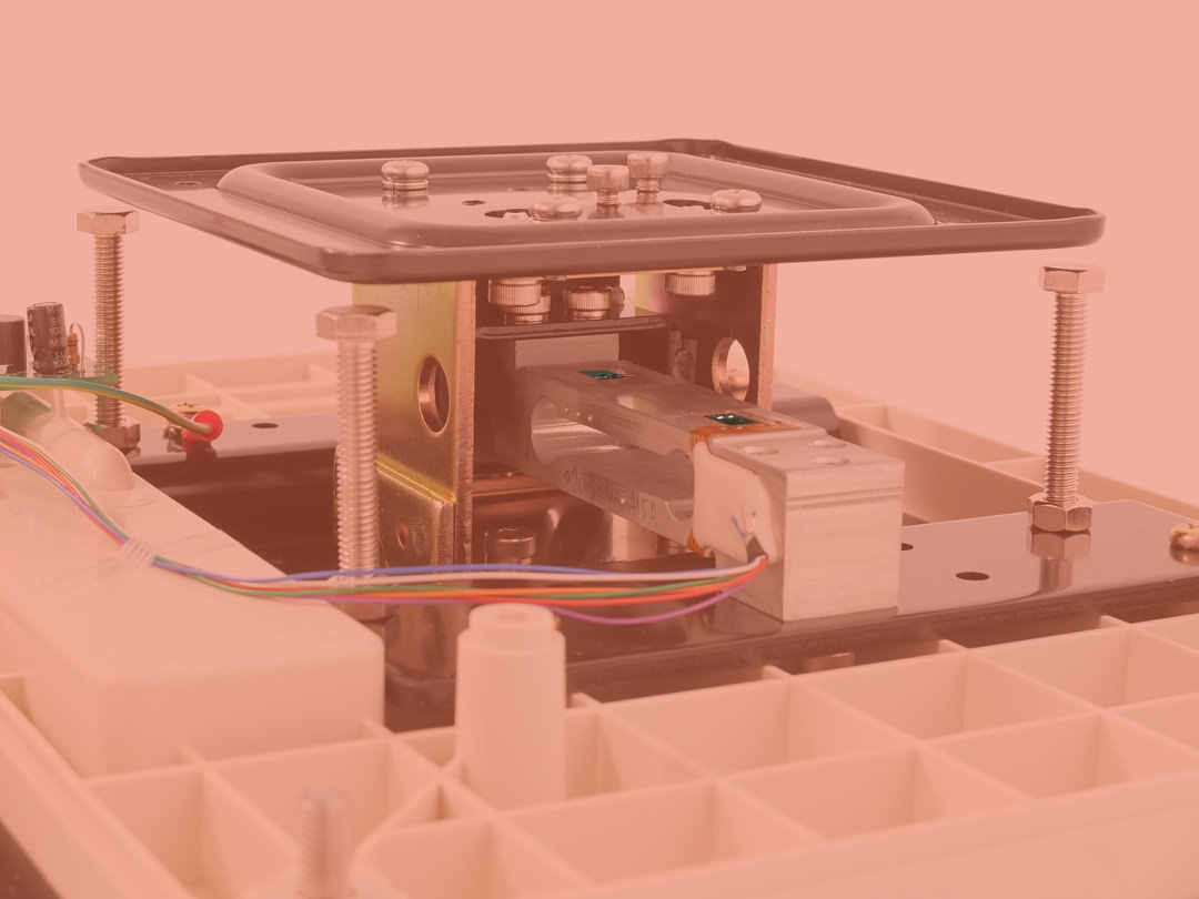
The deformation of the load cell is measured by tiny sensors called strain gauges. If you look closely (or click on the image to see it in full size), you can see two of them on top of the load cell while two more are located on the bottom side.
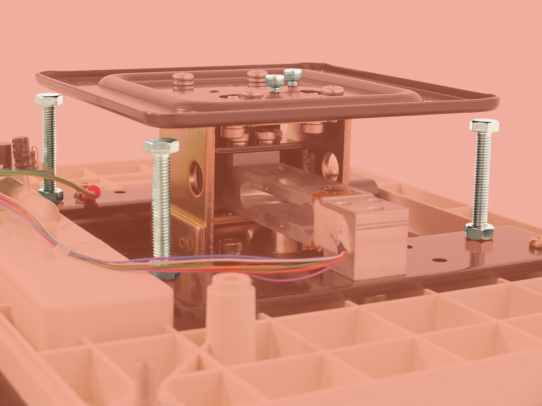
The overload stops prevent the load cell form deforming too far when a load beyond its capacity is applied. The two screws on the top are used to slightly tilt the top plate in order to adjust the overload gap between the plate and the 4 corner stops.
Please don’t hesitate to leave a comment and let me know if you’d like to see more interactive images.